Engineering Selection and System Integration for BLDC Motors
For engineering, purchasing, and OEM teams: do not select a motor based on power alone. Evaluate cost, torque, control, feedback, cooling, and mechanical integration as one system.
Once a BLDC motor appears to be a good fit for a machine, the next question is not "Which motor can we install?" The better question is: "How should the motor, driver, sensor, and mechanical load work together so the complete machine performs better?"
Core idea: BLDC selection is not just motor selection; it is system selection.
1. Do Not Compare Motor Prices Alone: Look at CAPEX and TCO
Many buyers compare motor unit prices first. For industrial machinery, however, the more meaningful comparison is the complete drive system.
- CAPEX: the upfront cost required to build or purchase the equipment.
- TCO (Total Cost of Ownership): the total cost over the equipment's operating life.
TCO can include the motor, driver, variable-frequency drive (VFD), gearbox, belts, pulleys, control cabinet, assembly labor, energy use, maintenance, downtime, and replacement parts.
The right comparison is AC Motor System vs. BLDC Motor System, not simply AC Motor vs. BLDC Motor.
2. Direct Drive: Design for Torque and Speed, Not Just Gearbox Removal
Conventional machines often use a high-speed motor and reduce speed through belts and gearboxes.
This is a mature and reliable approach, but it adds mechanical parts, maintenance, and installation space.
AC Motor → Belt / Pulley → Gearbox → Machine
If the BLDC motor is redesigned around the actual speed and torque required by the mechanism, the drivetrain may be simplified.
BLDC Motor + Driver → Machine
This may reduce the BOM, lower maintenance requirements for belts or gears, reduce machine size, or potentially improve efficiency and control. But feasibility must be verified using continuous torque, peak torque, startup load, minimum speed, and thermal conditions.
3. BOM and Mechanical Simplification: Motor Selection Can Change the Whole Machine
The value of a customized BLDC solution does not come simply from replacing an AC motor. It is an opportunity to rethink the machine's overall component layout.
- Can the belt and pulley be eliminated?
- Can the gearbox be reduced in size?
- Can the driver be integrated closer to the motor?
- Can the control cabinet be smaller and the wiring be simplified?
- Can installation space and service access be improved?
If these components can be integrated or simplified, a solution with a higher motor unit price may still be more competitive in terms of total machine CAPEX or TCO.
4. Motor + Driver + Sensor: Treat Them as One System
Driver → Motor → Mechanical Load
Feedback path: Sensor / Feedback → Driver
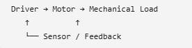
The feedback signal returns to the driver; it is not a separate component in a one-way series path.
The same motor can behave differently with a different driver. The same motor-and-driver combination can also show very different low-speed stability, position accuracy, and dynamic response when the feedback sensor changes.
For industrial machinery, "48 V, 1 kW, 3000 rpm" is usually not enough information for proper selection. It does not tell us how the machine starts, what load it experiences, what the minimum operating speed is, or how precise the control must be.
5. Hall Sensor, Encoder, or Sensorless Control?
Feedback Method | Best-Fit Situation | Main Advantage | Engineering Considerations
Hall Sensor | Basic commutation and general speed control | Simple, mature, and lower cost | Limited low-speed precision and position information
Encoder | Higher-resolution feedback for speed or position control | Supports closed-loop control | Cost, wiring, installation, and environmental suitability must be verified
Sensorless | Selected fan, pump, and compressor applications with suitable startup and low-speed requirements | Fewer sensors and wires; simpler structure | Startup and low-speed control require special validation
Encoders are not all the same. Magnetic encoders are usually compact and easy to integrate. Optical encoders can provide high resolution. Absolute encoders can report absolute shaft position immediately after power-up. The right choice depends on resolution, accuracy, environment, EMI, temperature, and cost.
Resolution and accuracy are different specifications and should not be treated as interchangeable.
6. How FOC and the Driver Affect System Performance
FOC stands for Field-Oriented Control. For readers without a control-systems background, it can be understood as a method that allows the driver to control the motor's magnetic field and torque more precisely.
- Torque output can be smoother.
- Low-speed control and speed stability can be improved.
- Torque ripple and noise can be reduced in suitable systems.
- It can support applications that require fast dynamic response.
However, seeing "FOC" on a driver specification does not mean every FOC system will perform the same. Motor parameters, current control, sensor choice, switching frequency, software tuning, and the load all affect the final result.
Engineering rule: "FOC" alone is not enough. The motor and driver must be properly matched.
7. Inner Rotor vs. Outer Rotor: Engineering Trade-Offs
Inner Rotor: generally favors high-speed operation, lower inertia, and fast response
Outer Rotor: may suit certain low-speed, high-torque, or direct-drive layouts
| Comparison |
Inner Rotor |
Outer Rotor |
| Rotor Inertia |
Usually lower |
Usually higher |
| Dynamic Response | Good for rapid acceleration, deceleration, and reversing | Well suited to steady output and higher-torque requirements |
| High-Speed Design | Generally easier | Requires more attention to balance, mechanical strength, and centrifugal forces |
| Packaging | A conventional cylindrical package is common | Can integrate directly with fans, hubs, and similar mechanisms |
| Typical Applications | Power tools, spindles, servo systems | Fans, hubs, and selected low-speed, high-torque systems |
These are general tendencies, not absolute rules. The final choice should be based on the required speed, torque, inertia, package, and mechanical constraints.
8. Radial Flux vs. Axial Flux: Newer Is Not Automatically Better
Radial Flux: mature, scalable, and widely used
Axial Flux: useful for flat-package designs or selected high-torque-density requirements
| Comparison |
Radial Flux |
Axial Flux |
| Maturity |
High; the supply chain and manufacturing processes are well established |
Depends on design; production challenges are often higher |
| Package Shape | Cylindrical form is common | Axial length can be shorter |
| Torque Density | Compare torque density for the target design; do not infer performance from topology alone | Compare torque density for the target design; do not infer performance from topology alone |
| Manufacturing | Mature processes are widely available | Tolerances, assembly, and magnetic-circuit design can be more complex |
| Thermal / Structural Design | Many proven solutions are available | Cooling and structural design require more careful attention |
Selection principle: Do not choose an axial-flux design simply because it is newer. First ask: "Does the product have a problem that axial flux solves more effectively?"
9. Why kW or HP Alone Is Not Enough
Two machines can both use a 2 HP motor and still have completely different operating requirements.
A fan may run steadily for long periods. A hoist may require high starting torque and short-duration overload capability. A machine tool may accelerate and decelerate frequently.
The key, therefore, is not rated power alone. Engineers need to understand the load profile: how the load changes throughout the complete operating cycle.
A practical starting point: Describe one complete machine operating cycle before selecting the motor.
10. From Motor Specifications to Machine Requirements
By this stage, it should be clear why kW or HP alone cannot fully define a motor's requirements. The next step is to translate the machine's operating profile into information that a supplier can evaluate. A useful RFQ describes not only the motor's nominal rating but also how the machine starts, runs, accelerates, and handles abnormal loads.
First determine whether the RFQ is for a motor + controller package or for the motor only. For a motor + controller package, specify the controller input voltage and whether the supply is single-phase or three-phase. Then define the motor's rated power, rated speed, rated torque, minimum and maximum operating speeds, and whether field-weakening operation is required above rated speed. Motor frequency is not normally a selection parameter for a BLDC/PMSM system because speed is electronically controlled by the driver.
Next, define the duty profile. State the duty classification, such as S1, S2, or S3, and the actual operating duration or ON/OFF cycle. If overload is required, specify the overload torque, the speed at which it occurs, the allowable overload duration, and the minimum recovery interval before the next overload event. Also include starts, stops, reversals, load inertia, acceleration time, and the transmission arrangement if applicable.
Environmental and mechanical conditions are equally important. State the cooling method, ambient temperature, IP target, exposure to water, dust, or oil mist, noise limit and measurement conditions, expected service life, bearing conditions, and maintenance interval. Also provide the available installation space, motor outer diameter, length, flange dimensions, shaft diameter, and shaft length.
For a motor-only RFQ, describe the existing controller or inverter conditions. Provide the available DC-bus voltage, control method (such as FOC), required feedback device and interface, and any motor parameters the controller requires, such as back-EMF constant, phase resistance, phase inductance, rated current, and peak current. This allows the motor to be matched to the customer's controller rather than treated as an isolated component.
11. Two Simple RFQ Examples
Example A - Motor + Controller:
Controller input: 220-240 VAC, single-phase; rated motor output: 1 kW; rated speed: 1800 rpm; rated torque: 5.3 Nm; operating speed range: 200-2700 rpm; required constant-torque range: 200-1800 rpm, up to 5.3 Nm; field-weakening range: 1800-2700 rpm (up to 150% of rated speed). Above 1800 rpm, operation is approximately constant-power, so continuous torque decreases to about 3.5 Nm at 2700 rpm if 1 kW output is maintained. Normal duty: S1 at 5.3 Nm and 1800 rpm; short-time overload: 8.0 Nm at 1800 rpm for up to 10 seconds, followed by at least 50 seconds at rated load or below before the next overload event; feedback: encoder; cooling: natural cooling; ambient temperature: 0-40°C; protection: IP54; control interface: 0-10 V speed command and digital Forward/Reverse input.
Example B - Motor Only:
Rated motor output: 1 kW; rated speed: 1800 rpm; rated torque: 5.3 Nm; required operating speed range: 200-2700 rpm; normal duty: S1 at 5.3 Nm and 1800 rpm; short-time overload: 8.0 Nm at 1800 rpm for up to 10 seconds, followed by at least 50 seconds at rated load or below before the next overload event; available controller DC bus: 310 VDC; control method: FOC; feedback: incremental encoder. The motor supplier should provide or confirm the back-EMF constant, phase resistance, phase inductance, rated current, peak current, encoder interface, and suitability for field-weakening operation up to 2700 rpm. Cooling: natural cooling; ambient temperature: 0-40°C; protection: IP54.
12. Yen Shen Engineering: Potential Areas of Engineering Support
For OEM and ODM industrial equipment, the motor does not have to be a standard component selected at the end of the design process. Starting with machine requirements creates an opportunity to review performance, size, control, and cost together.
Depending on the project scope, Yen Shen's engineering team can support:
- Customized BLDC / PMSM motor design
- Driver and motor matching
- Hall / Encoder / Sensorless feedback integration
- Low-speed, high-torque, and direct-drive evaluation
- Mechanical interface and package customization
- Cooling, IP protection, and environmental evaluation
- Feasibility evaluation for converting AC Motor + VFD systems to customized BLDC / PMSM solutions
Machine Requirements
→ Motor + Driver + Sensor
→ Mechanical Integration
The most important sequence is to understand the machine requirements first. Then define the motor, driver, sensor, and mechanical system instead of starting from a motor catalog and choosing the closest model.
Conclusion: A Good BLDC Project Optimizes the Complete System
A common mistake in industrial BLDC selection is to focus only on power and speed. In practice, success often depends on torque requirements, load inertia, duty cycle, minimum speed, cooling, IP protection, feedback, and how the driver controls the motor.
Once these conditions are clearly defined, the motor, driver, sensor, and mechanical system can be optimized together. This is where a customized BLDC / PMSM solution may create the most value.
Contact Yen Shen Engineering
If you are developing a new machine or evaluating a conversion from an AC Motor + VFD system to a BLDC / PMSM solution, share your requirements for torque, speed, duty cycle, voltage, control, installation space, and operating conditions with our engineering team. We can discuss whether a customized approach is suitable for the application.
Yen Shen Engineering | Customized BLDC Motor Solutions